- 您现在的位置:买卖IC网 > Sheet目录17382 > MAX4821ETP+T (Maxim Integrated Products)IC RELAY DRIVER 8CHAN 20-TQFN
MAX4820/MAX4821
+3.3V/+5V, 8-Channel, Cascadable Relay Drivers
with Serial/Parallel Interface
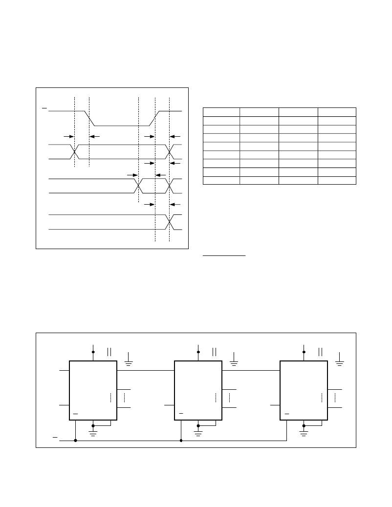
Table 2. Parallel Interface Address Map
(MAX4821 Only)
CS
A2
Low
Low
A1
Low
Low
A0
Low
High
OUTPUT
OUT1
OUT2
t AS
t AH
Low
High
Low
OUT3
A_
LVL
t LS
t LH
Low
High
High
High
High
High
Low
Low
High
High
High
Low
High
Low
High
OUT4
OUT5
OUT6
OUT7
OUT8
SET / RESET Functions
t ON ,
t OFF
V OUT
Figure 2. Parallel Interface Timing Diagram (MAX4821 only)
The MAX4820/MAX4821 feature set and reset inputs that
allow the user to simultaneously turn all outputs on or off
using a single control line. Drive SET low to set all latch-
es and registers to 1 and turn all outputs on. SET over-
rides all serial/parallel control inputs. Drive RESET low to
clear all latches and registers and turn all outputs off.
RESET overrides all other inputs, including SET .
Applications Information
Daisy Chaining
The MAX4820 features a digital output, DOUT, that pro-
vides a simple way to daisy chain multiple devices. This
feature allows the user to drive large banks of relays
using only a single serial interface. To daisy chain multi-
ple devices, connect all CS pins together, and connect
the DOUT of one device to the DIN of another device
(see Figure 3). During operation, a stream of serial data
V CC
0.1 μ F
V CC
0.1 μ F
V CC
0.1 μ F
V CC
V CC
V CC
DIN
DIN
DOUT
DIN
DOUT
DIN
DOUT
MAX4820 OUT1
MAX4820 OUT1
MAX4820 OUT1
SCLK
SCLK
OUT8
SCLK
SCLK
OUT8
SCLK
SCLK
OUT8
CS
GND
PGND
CS
GND
PGND
CS
GND
PGND
CS
Figure 3. Daisy-Chain Configuration
8
Maxim Integrated
发布紧急采购,3分钟左右您将得到回复。
相关PDF资料
195D156X06R3X2T
CAP TANT 15UF 6.3V 20% 2910
TAC225K015P01
CAP TANT 2.2UF 15V 10% AXIAL
A9CCA-0504F
FLEX CABLE - AFG05A/AF05/AFG05A
EBM25DCMD
CONN EDGECARD 50POS .156 WW
195D156X0010X2T
CAP TANT 15UF 10V 20% 2910
EBM25DCCN
CONN EDGECARD 50POS R/A .156 SLD
195D107X96R3X2T
CAP TANT 100UF 6.3V 10% 2910
S5JHE3/57T
DIODE GPP 5A 600V SMC DO-214AB
相关代理商/技术参数
MAX4821ETP-T
功能描述:功率驱动器IC RoHS:否 制造商:Micrel 产品:MOSFET Gate Drivers 类型:Low Cost High or Low Side MOSFET Driver 上升时间: 下降时间: 电源电压-最大:30 V 电源电压-最小:2.75 V 电源电流: 最大功率耗散: 最大工作温度:+ 85 C 安装风格:SMD/SMT 封装 / 箱体:SOIC-8 封装:Tube
MAX4821EUP
功能描述:功率驱动器IC RoHS:否 制造商:Micrel 产品:MOSFET Gate Drivers 类型:Low Cost High or Low Side MOSFET Driver 上升时间: 下降时间: 电源电压-最大:30 V 电源电压-最小:2.75 V 电源电流: 最大功率耗散: 最大工作温度:+ 85 C 安装风格:SMD/SMT 封装 / 箱体:SOIC-8 封装:Tube
MAX4821EUP+
功能描述:功率驱动器IC 3.3-5V 8Ch Cascade Relay Driver RoHS:否 制造商:Micrel 产品:MOSFET Gate Drivers 类型:Low Cost High or Low Side MOSFET Driver 上升时间: 下降时间: 电源电压-最大:30 V 电源电压-最小:2.75 V 电源电流: 最大功率耗散: 最大工作温度:+ 85 C 安装风格:SMD/SMT 封装 / 箱体:SOIC-8 封装:Tube
MAX4821EUP+T
功能描述:功率驱动器IC 3.3-5V 8Ch Cascade Relay Driver RoHS:否 制造商:Micrel 产品:MOSFET Gate Drivers 类型:Low Cost High or Low Side MOSFET Driver 上升时间: 下降时间: 电源电压-最大:30 V 电源电压-最小:2.75 V 电源电流: 最大功率耗散: 最大工作温度:+ 85 C 安装风格:SMD/SMT 封装 / 箱体:SOIC-8 封装:Tube
MAX4821EUP-T
功能描述:功率驱动器IC RoHS:否 制造商:Micrel 产品:MOSFET Gate Drivers 类型:Low Cost High or Low Side MOSFET Driver 上升时间: 下降时间: 电源电压-最大:30 V 电源电压-最小:2.75 V 电源电流: 最大功率耗散: 最大工作温度:+ 85 C 安装风格:SMD/SMT 封装 / 箱体:SOIC-8 封装:Tube
MAX4822ETP
功能描述:功率驱动器IC RoHS:否 制造商:Micrel 产品:MOSFET Gate Drivers 类型:Low Cost High or Low Side MOSFET Driver 上升时间: 下降时间: 电源电压-最大:30 V 电源电压-最小:2.75 V 电源电流: 最大功率耗散: 最大工作温度:+ 85 C 安装风格:SMD/SMT 封装 / 箱体:SOIC-8 封装:Tube
MAX4822ETP+
功能描述:功率驱动器IC 3.3V/5V 8Ch Relay Driver RoHS:否 制造商:Micrel 产品:MOSFET Gate Drivers 类型:Low Cost High or Low Side MOSFET Driver 上升时间: 下降时间: 电源电压-最大:30 V 电源电压-最小:2.75 V 电源电流: 最大功率耗散: 最大工作温度:+ 85 C 安装风格:SMD/SMT 封装 / 箱体:SOIC-8 封装:Tube
MAX4822ETP+T
功能描述:功率驱动器IC 3.3V/5V 8Ch Relay Driver RoHS:否 制造商:Micrel 产品:MOSFET Gate Drivers 类型:Low Cost High or Low Side MOSFET Driver 上升时间: 下降时间: 电源电压-最大:30 V 电源电压-最小:2.75 V 电源电流: 最大功率耗散: 最大工作温度:+ 85 C 安装风格:SMD/SMT 封装 / 箱体:SOIC-8 封装:Tube
